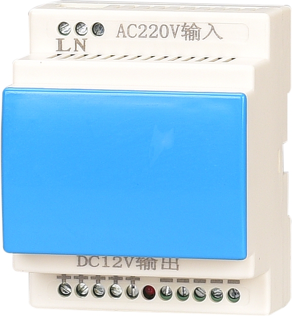
Chongqing Fire Equipment Power Sensor Fangdeng Liushi Manufacturer Electrical City Quotation _ Power Supply
The intelligent fire equipment power monitoring system is developed based on the national standard "Fire Equipment Power Monitoring System". The system consists of a fire equipment power status monitor, a power bus, a communication bus, and connected current signal sensors, voltage signal sensors, current/voltage signal sensors, intermediate module boxes, and other devices. Through sensors, the main and backup power supplies of the fire equipment are detected in real time to determine whether the power equipment has overvoltage, undervoltage, overcurrent, open circuit, short circuit, and phase loss faults. When a fault occurs, it can quickly display and record the location, type, and time of the fault on the monitor, and emit sound and light alarm signals, effectively ensuring the reliability of the fire linkage system in the event of a fire.

edit
GB28184-2011 "Fire Equipment Power Monitoring System"
The national standard GB28184-2011 "Fire Equipment Power Monitoring System" is under the jurisdiction of the national fire standardization technology fire detection and alarm sub technology. It was promulgated on December 28, 2011 and implemented on August 1, 2012. This standard mandates the basic functions of the power monitoring system for firefighting equipment;
2. The design atlas of the "Fire Equipment Power Monitoring System" compiled by the China Academy of Building Standards Design and Research;
The national standard GB25506-2010 "General Technical Requirements for Fire Control Rooms" organized and compiled by the Ministry of Fire Protection stipulates that the fire control room should be able to display the working status and undervoltage alarm information of the power supply and backup power supply of each fire electrical equipment in the system.
Scope of application:
Monitoring sensors are used to detect the voltage and current values of the AC power supply circuit for firefighting equipment (normal and backup power). The sensors have
The voltage and current value monitoring selection function can be set by users according to the monitoring requirements of the power supply circuit.
Main functions:
Real time monitoring of both common and backup power sources simultaneously
The communication between sensors and monitors adopts a bus system to set addresses
Randomly set parameters such as voltage value, current value, delay time, and fault alarm output
● Relay alarm output (adjustable)
● Meet the requirements of the national standard GB28184-2011 "Fire Equipment Power Monitoring System";
Monitor the working status of the power supply for firefighting equipment;

Monitor faults such as overvoltage, undervoltage, and overcurrent in the power supply of fire-fighting equipment;
● Monitor power interruption and power failure of fire-fighting equipment;
Adopting DC24V working voltage to ensure system and personal safety;
Collect voltage and current signals of the monitored circuit directly with an error of less than 1%;
● Optional residual current monitoring function.
Power supply voltage: DC24V is centrally supplied by the regional extension or host
Bus communication method: CAN bus
Power line+communication line: NH-BV-2 * 2.5mm2 (power line)+ZR-RVS-2 * 1.5mm2 (communication line)
Output parameters: 1 passive contact, alarm or control output
Address code: Each sensor has an address code, which is randomly set
Isolator: Each sensor comes with its own isolator
Alarm delay: adjustable from 0 to 30 seconds, can be set on site

Alarm parameters: 85% of undervoltage rated voltage, 110% of overvoltage rated voltage: overcurrent according to the current transformer ratio setting value of 25%
Alarm display: LED display with sound and light alarm
Environmental temperature: -20 ℃~+70 ℃
Protection level: P30

Installation method: Standard 35mm rail installation
Flexibly build a capacity fire equipment power monitoring system by connecting with the upper computer, domain extension, signal acquisition module, etc; The system adopts a non open operation mode, with self-management within the system and one-way transmission of information to the outside world; Adopting a centralized power supply method to provide DC24V safe voltage to on-site modules, effectively ensuring the stability and safety of the system; The output circuit can be flexibly expanded through domain extensions to meet the complex and ever-changing requirements of modern architecture; Monitor the working status and fault alarm information of all fire-fighting equipment and backup power sources, and transmit the working status and alarm information to the graphic display device in the fire control room; The system has the characteristics of reliability, timeliness, and continuous monitoring with digitization, intelligence, networking, and automation. Reflecting the power status of the monitored equipment and displaying it in a centralized manner can effectively avoid the danger of firefighting equipment being unable to function properly due to power failure during a fire, thus ensuring the reliability of the firefighting linkage system to the fullest extent possible; The series fire equipment power monitoring system adopts a three-layer network structure of electrical equipment+monitoring module+system machine, which simplifies the system structure design. The entire monitoring system is safe, reliable, accurate in detection, and cost-effective. The system uses CAN network communication internally and provides Modbus RTU communication protocol externally to meet the connection requirements of other standard systems; The entire series of sensors are powered by a 24V DC safe voltage, ensuring both personal safety and stable operation of the entire system;
