Shanghai South Campus Equipment Calibration - Calibration Center - Transmitter
Calibration specifications for temperature transmitters:
1. Scope: The "Calibration Specification for Temperature Transmitters JJF 1183-2007" is applicable to temperature transmitters with sensors such as thermocouples or thermal resistors. Temperature transmitters include those with and without temperature sensors.
2. Overview:
A temperature and humidity transmitter is an instrument that converts temperature variables into standardized output signals that can be transmitted. Mainly used for measuring and controlling temperature parameters in industrial processes.
3. A temperature transmitter with a sensor (integrated temperature transmitter) usually consists of two parts: a sensor and a signal converter. Sensors are mainly thermocouples and thermistors; Signal converters are mainly composed of measurement units, signal processing units, and conversion units (due to the standardization of industrial thermocouples and thermal resistance calibration tables, signal converters also become temperature transmitters when used alone as products). Some temperature transmitters have added display units, and some also have fieldbus functions.
Instrument calibration equipment calibration equipment verification equipment calibration
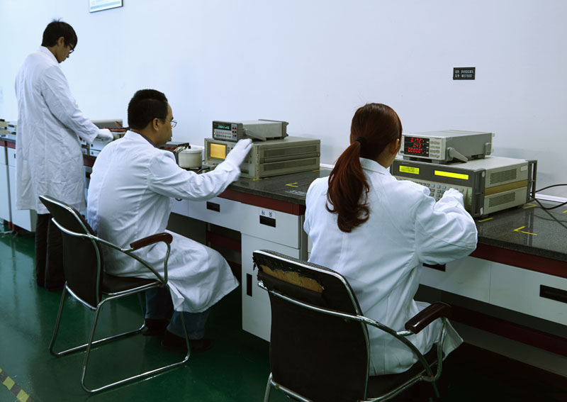
If a temperature transmitter consists of two sensors used to measure temperature differences, and there is a given continuous functional relationship between the output signal and the temperature difference, it also becomes a temperature difference transmitter. There is a given continuous function relationship (usually referred to as a linear function) between the output signal of a temperature transmitter and the temperature variable. Early produced temperature transmitters had a linear function relationship between their output signal and the resistance value (or voltage value) of the temperature sensor. The standardized output signals mainly consist of 0-10mA and 4-20mA DC current signals. Other standardized signals with special regulations cannot be excluded.
5.1 Calibration Environmental Conditions
The ambient temperature is 15-35 ℃; Relative humidity.
To ensure that calibration has as little uncertainty as possible, it is recommended that calibration be carried out under the following standard environmental conditions. These conditions are also conducive to providing an explanation of whether the instrument measurement characteristics are met when requested by the user.
a) Environmental temperature of 20 ℃± 2 ℃ (0.1-0.2 level transmitter); 20 ℃± 5 ℃ (0.5-2.5 level transmitter).
b) Relative humidity is 45-75%.
c) There should be no external magnetic field around the temperature transmitter that affects normal operation, except for the geomagnetic field.
5.2 Power Supply: The working power supply of the transmitter is an AC powered transmitter, with a voltage variation not exceeding ± 1% of the rated value and a frequency not exceeding ± 1% of the rated value; The voltage variation of a DC powered transmitter shall not exceed ± 1% of the rated value.
Instrument calibration, instrument calibration, instrument measurement
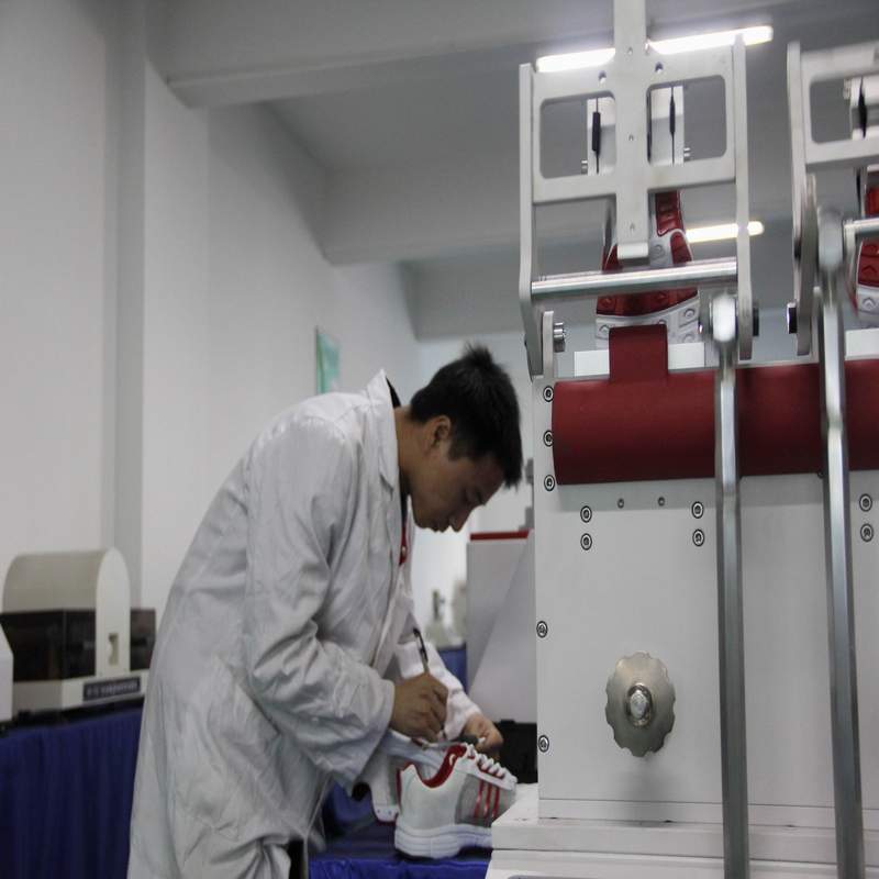
Temperature transmitter calibration items:
a) The calibration items for the transmitter are measurement error and insulation resistance measurement.
b) Newly manufactured transmitters without sensors should also undergo insulation strength measurement.
c) For DDZ series transmitters, according to the requirements of the client, load characteristics, power supply effects, and output AC components can also be measured according to Appendix B.
6.2 Calibration method for temperature transmitter:
6.2.1 Calibration of measurement errors
6.2.1.1 Preparation work
a) Equipment configuration and connection
The transmitter with sensor inserts the sensor into the temperature source (thermostatic bath or thermocouple calibration furnace) and is placed as close as possible to the standard thermometer. The connection between the transmitter calibration and the standard and supporting equipment is shown in Appendix A.
b) The preheating time for power on should be carried out according to the manufacturer's instructions, usually 15 minutes; The one with automatic compensation for reference temperature is 30 minutes.
c) Adjustment before calibration.
The transmitter without sensors can adjust the corresponding output lower and upper limit values by changing the input signal, so that they are consistent with the theoretical lower and upper limit values (adjustments must be made with the consent of the client).
For transmitters with adjustable input range, the input specifications and range should be adjusted to the specified values according to the client's requirements before calibration.
The transmitter with a sensor can make the above adjustments to the signal converter separately without disconnecting the sensor. If the measurement results still cannot meet the requirements of the client, they can be readjusted in a constant temperature bath or thermocouple calibration furnace.
Zero and range adjustments are not allowed during the measurement process.
Note: (1) General transmitters can be adjusted by adjusting the "zero point" and "full range".
(2) The transmitter with fieldbus must adjust the "zero point" and "full range" of the input and output parts separately through a manual controller (or adapter) according to the instructions to complete the adjustment work. At the same time, the damping value of the transmitter should be adjusted to * small.
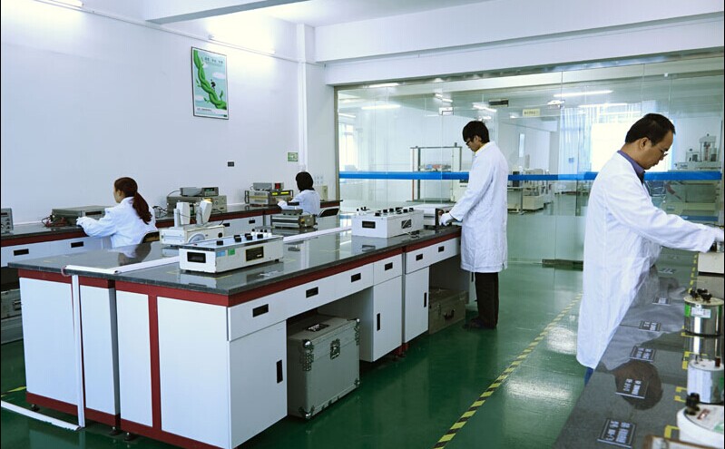
Shanghai South Campus Equipment Calibration - Calibration Center - Temperature Transmitter Calibration
Selection of calibration points: The selection of calibration points should be evenly distributed according to the range, generally including no less than 5 points including upper limit value, lower limit value, and around 50% of the range. Transmitters with a rating of 0.2 or higher should have no less than 7 points.
a) When calibrating a transmitter with sensors, the measurement sequence can start from the lower limit temperature of the measurement range, and then measure from bottom to top. At each test point, measurements can only be taken after the temperature inside the temperature source is stable enough (generally not less than 30 minutes): the readings of the standard thermometer and the transmitter output should be repeated 6 times alternately. Calculate the measurement error according to equation (1):
Formula (1)
1. Measurement error of each calibration point of the transmitter (expressed as output quantity), mA or V;
2. The average value of the actual output of the calibrated transmitter, in mA or V;
3. The output range of the transmitter, in mA or V;
4. Input range of transmitter, ℃;
5. Theoretical lower limit value of transmitter output, mA or V;
6. The average temperature value measured by a standard thermometer, ℃;
7. The lower limit value of the transmitter input range, ℃.
b) When calibrating a transmitter without sensors, the signal values corresponding to each calibration point should be smoothly input from the lower limit, and the output values should be read and recorded until the upper limit; Then smoothly change the input signal in the opposite direction to each calibration point, read and record the output value until the lower limit. So for one cycle, three cycles of measurement are required. When approaching the calibration point, the input signal should be slow enough to avoid overshoot.
Note: When calibrating a transmitter with reference temperature automatic compensation for thermocouple input, in order to obtain an integer standard output value, the input signal of each calibration point should be the electrical value corresponding to the calibration point minus the correction value of the compensation wire.
The measurement error is calculated according to equation (2):
1. The transmitter is calibrated for actual output, and the average of multiple measurements is taken in mA or V;
2. The output range of the transmitter, in mA or V;
3. Input range of transmitter, ℃;
4. Theoretical lower limit value of transmitter output, mA or V;
5. The input temperature value of the transmitter, which is the temperature value corresponding to the analog thermistor (or thermocouple), in ℃;
6. The lower limit value of the transmitter input range, ℃;
7. Compensation wire correction value, mV;
8. The temperature measurement points and slopes of the thermocouple characteristic curve can be regarded as constants for a certain temperature measurement point, mV/℃.
6.2.1.3 Processing of measurement results: Measurement errors can be expressed in units of output, temperature, or as a percentage of input (or output). Since the output of the transmitter is usually a linear function of temperature, the conversion between them can be done according to equation (3): - the error represented by the input temperature, ℃.
Note: Some products in the DDZ series transmitters output a linear function of the millivolt signal of the thermocouple (or the resistance signal of the thermistor). At this point, t in equations (1) - (3) should be replaced by a millivolt signal (or resistance signal).
Instrument testing, instrument calibration, instrument verification and calibration
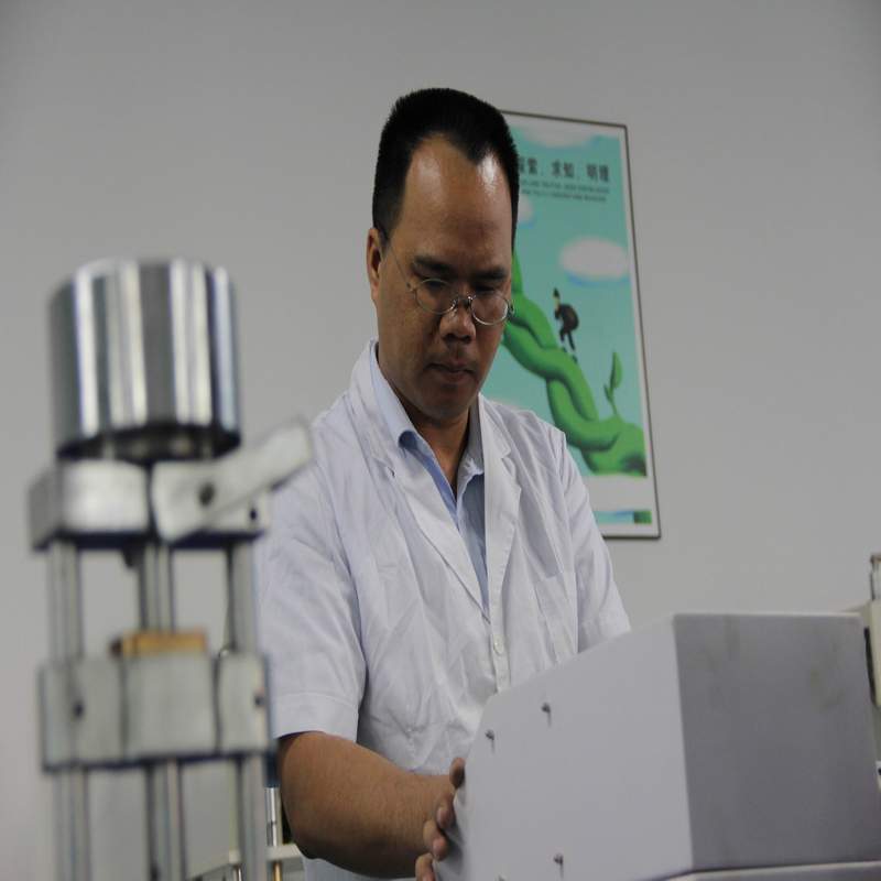
6.2.2 Measurement of Insulation Resistance:
Disconnect the power supply of the transmitter and measure with an insulation resistance meter at the location specified in Table 2. The measurement should be stable for 5 seconds before reading.
6.2.3 Measurement of Insulation Strength:
Disconnect the power supply of the transmitter and connect each pair of wiring terminals to the two poles of the voltage tester in sequence according to the provisions of Table 3, slowly and steadily lowering to zero.
Note: To protect the transmitter from breakdown during testing, a voltage withstand tester with an alarm current setting can be used during testing. The set value is generally 5mA (except for special requirements). When using this instrument, the alarm is used as the basis to determine whether the insulation strength is qualified or not. (ywd811926dgst)
6.3 Data processing principles:
Principle of data processing in measurement results and error measurement process: The number of decimal places retained after the decimal point should be limited to rounding errors less than 1/10 to 1/20 of the transmitter's allowable error (equivalent to taking one decimal place more than the allowable error).
In the calculation of uncertainty, to avoid rounding errors, 2-3 significant digits can be retained. But the final expansion uncertainty can only retain 1-2 significant digits. The measurement result is given by the arithmetic mean of multiple measurements, and its last digit should be aligned with the significant digits of the extended uncertainty.
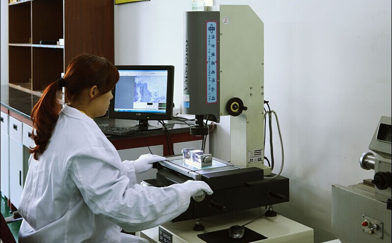
Regarding Shitong:
Third party calibration and measurement institution - Shitong Instrument Testing and Calibration Company, CNAS accreditation numbers: L3170 and L6634, a fifteen year old qualification testing institution with thirteen branches nationwide. Engineers can be arranged nationwide to provide on-site calibration services, issuing calibration labels and certificate reports. At the end of each month, internal calibration staff training is provided, and internal calibration staff certificates are issued. Through instrument and equipment calibration, various enterprise units can pass ISO, CCC, UL certifications, customer audits, factory audits, and more. Local calibration institutions are worth recommending and learning about. Welcome to call for consultation and cooperation.
以上信息由企业自行提供,信息内容的真实性、准确性和合法性由相关企业负责,仪器仪表交易网对此不承担任何保证责任。
温馨提示:为规避购买风险,建议您在购买产品前务必确认供应商资质及产品质量。